Differential Reaction Fingerprint
Introduction
Reaction transformation information is very useful for reaction data mining, it can be used for reaction classification and reaction similarity search and retrieval of knowledge for synthesis design. Traditional reaction classification techniques use atom-mapping to find the transformation between reactants and products. However correctly do a reaction atom mapping is difficult and time-consuming. Reaction vector is another type of reaction fingerprint and it has been used for clustering and similarity assessment of metabolic reactions or for de novo design of synthetically feasible molecules, but it is not easy to and store in database. Differential Reaction fingerprint(DRFP) is a very useful strategy to encode and represent the transformation of a reaction(also called reaction center), it doesn't need atom-mapping to differentiate between reactants and reagents. And, it is easy to extract and store in database. This article will introduce differential reaction fingerprint and talk about it's application for reaction data mining.
Definition of Differential Reaction Fingerprint
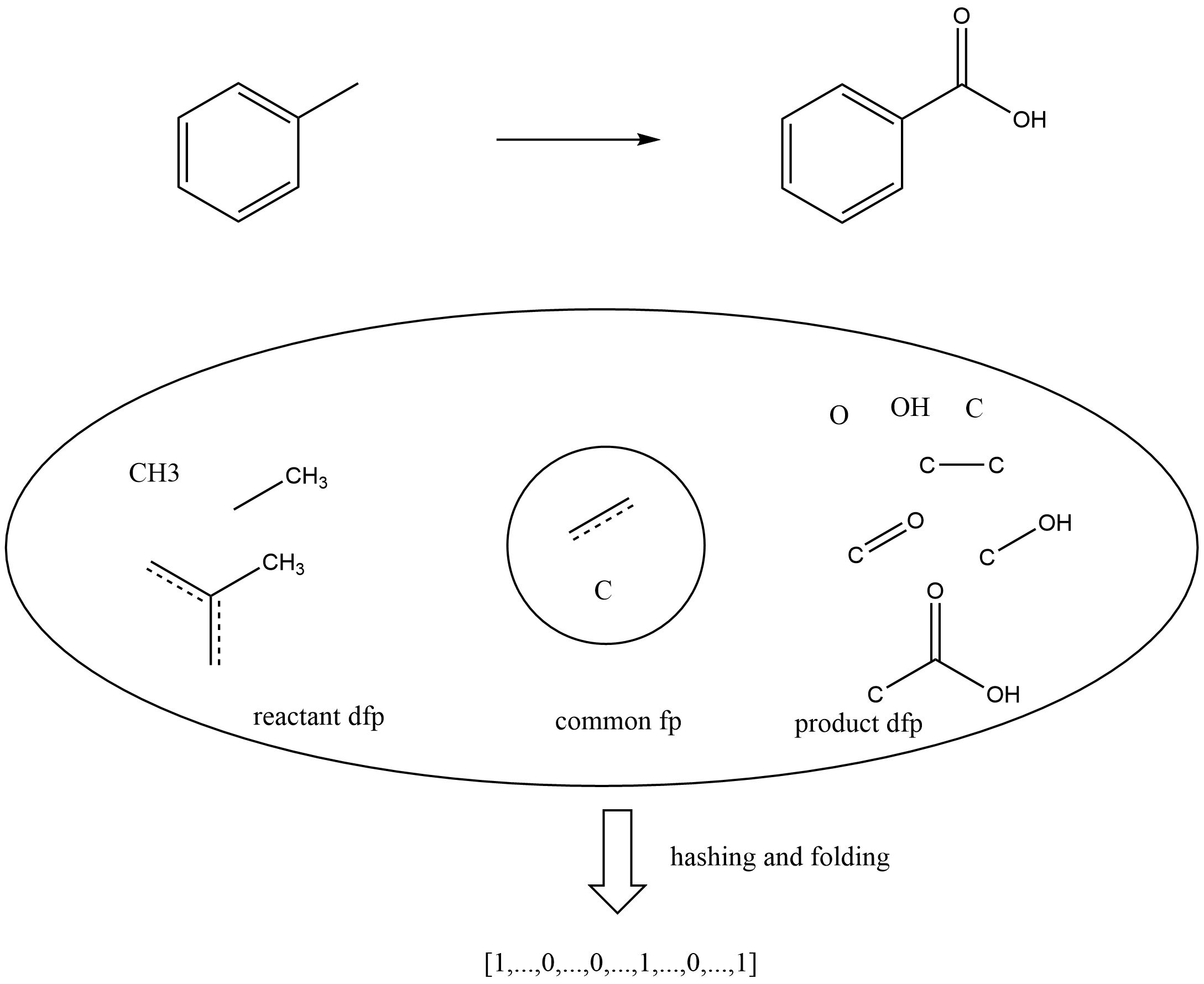
In general, the differential reaction fingerprint is defined as the difference of the chemical fingerprints of reactants and products. DRFP is very similar to Chemaxon reaction fingerprint, but that not only contains reaction center fingerprints but also store reactant and product features. DRFP in this article can be considered as a simplified representation of Chemaxon reaction fingerprint. As shown in below figure, reaction, it is a example of DRFP(only consider one bond neighborhood). Firstly, get all one bond neighborhood circular fingerprints of reactants and products, then remove common fingerprints to obtain the reaction center fingerprints, finally encode reaction center fingerprints using an arbitrary hash function with a sufficiently low collision probability and folded into a fix-length (1024 or 2048 in Ferrocene toolkit, first half is reactants DRFP, second half is products DRFP) binary vector to generate DRFP.
Application
Reaction Classification
Reaction classification is very useful in chemical data mining, many approaches were applied for it, but most of these approaches are based atom mapping, while the atom mapping problem is known to be NP hard. DRFP is easy to calculate and it doesn't need atom mapping, and it also contains the reaction transformation in information, so it is a good idea to use DRFP for reaction classification. Reymond et al have applied it to reaction classification and reach a good performance(DRFP + multilayer perceptron (MLP) classifier).
Reaction Search
If reactions are classified, them can be used for reaction search. But if you don't want to do classification firstly or you don't familiar with reaction classification algorithms, you also can using DRFP to do a reaction search directly. Because the DRFP contains the transformation information, so if two two DRFPs are similar, the original reactions are also similar and they are the same reaction class with a high probability.
Force-directed Layout Algorithms for Molecule 2D Coordinates Generation
Introduction
Force-directed graph layout algorithms are widely used in graph visualization. The concept was first introduced by Tutte based on barycentric representations. The essential spring layout methods which rely on spring forces are similar to those in Hooke’s law, there are repulsive forces among all vertices and also attractive forces among adjacent vertices. Alternatively, spring forces can be computed based on their graph theoretic distances. Graphs drawn with these force-directed algorithms tend to be aesthetically pleasing, exhibit symmetries, and most likely to produce crossing-free layouts for planar graphs. In my cheminformatics toolkit Ferrocene, forced-directed graph layout algorithm is used for complex ring system layout. this article will talk about the details of it in Ferrocene toolkit.
What is Force-directed Graph Layout ?
The algorithm is based on a physical model. Nodes are represented as points in a plane that are electrically charged and apply repulsive forces against each other. Edges connect these points simulating a spring-force, attracting adjacent nodes. The model iteratively determines the resulting forces that act on the nodes and try to move the nodes closer to an equilibrium where all forces add up to zero, and the position of the nodes stays stable.
In various of Force-directed layout algorithms, Fruchtermann-Reingold (FR), Kamada-Kawai (KK) and Stress Majorization are most popular. The advantage of the algorithm lies in the simplicity of the implementation. More, it works rather well for most graphs.
Force-directed Graph Layout in Molecule Coordinates Generation
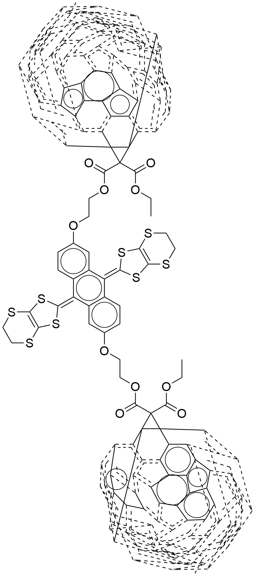
For molecules with complex ring system, it is not easy to generate proper 2d coordinates rapidly, some algorithms using molecule simulation or optimization-based algorithm to generate 3d coordinates firstly, then project to 2d space, these algorithm generate better coordinates, but the molecule simulation procedure will take long time. It can't used to generate coordinates for a mass of molecules. In Ferrocene toolkit force-directed graph layout is used to place complex ring system of a molecule. For below molecule, it has two complex ring systems, traditional structure diagram generation algorithms can't correctly place it if doesn't use template-based algorithm.
CCOC(=O)C1(C(=O)OCCOc2ccc3c(=C4SC5=C(SCCS5)S4)c4cc(OCCOC(=O)C5(C(=O)OCC)C67c8c9c%10c%11c%12c%13c(c%14c%15c6c6c8c8c%16c9c9c%10c%10c%12c%12c%17c%13c%13c%14c%14c%15c%15c6c6c8c8c%16c%16c9c9c%10c%12c%10c%12c%17c%13c%13c%14c%14c%15c6c6c8c8c%16c9c%10c9c%12c%13c%14c6c89)C%1157)ccc4c(=C4SC5=C(SCCS5)S4)c3c2)C23c4c5c6c7c8c9c(c%10c%11c2c2c4c4c%12c5c5c6c6c8c8c%13c9c9c%10c%10c%11c%11c2c2c4c4c%12c%12c5c5c6c8c6c8c%13c9c9c%10c%10c%11c2c2c4c4c%12c5c6c5c8c9c%10c2c45)C713
But forced-directed layout algorithms can generate better correct and readable coordinates. For above structure smiles, the left image is created by Ferrocene toolkit that use force-directed algorithm to place C60 fragment, right is generated by ChemDraw.
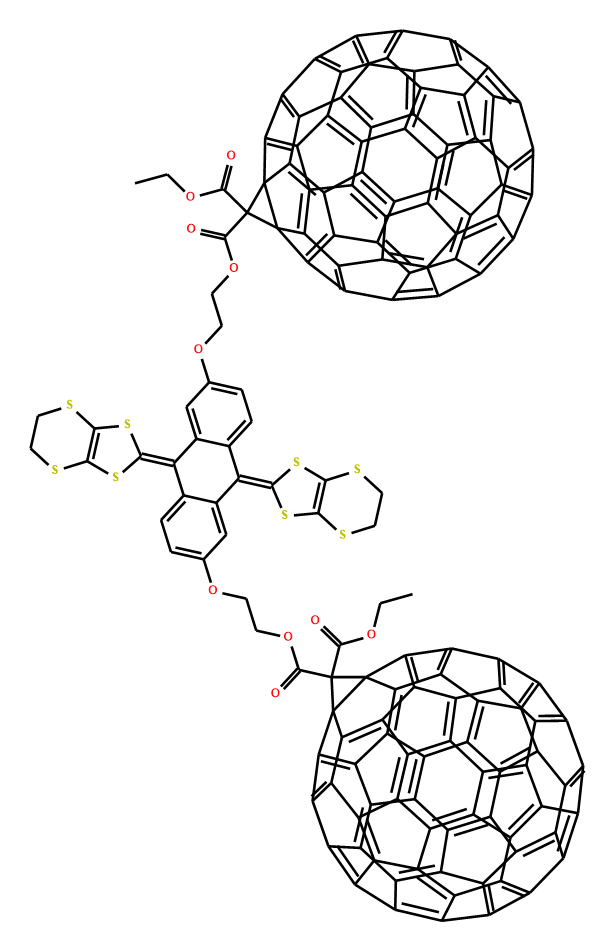
force-directed layout(generated by Ferrocene toolkit) and traditional layout(generated by ChemDraw)
Comparison of Forced-directed Graph Layout for Molecule Coordinates Generation
There are various forced-directed layout algorithms, which is better for molecule coordinates generation ? Three algorithms are implemented in Ferrocene toolkit: Fruchtermann-Reingold, Kamada-Kawai and Stress Majorization.
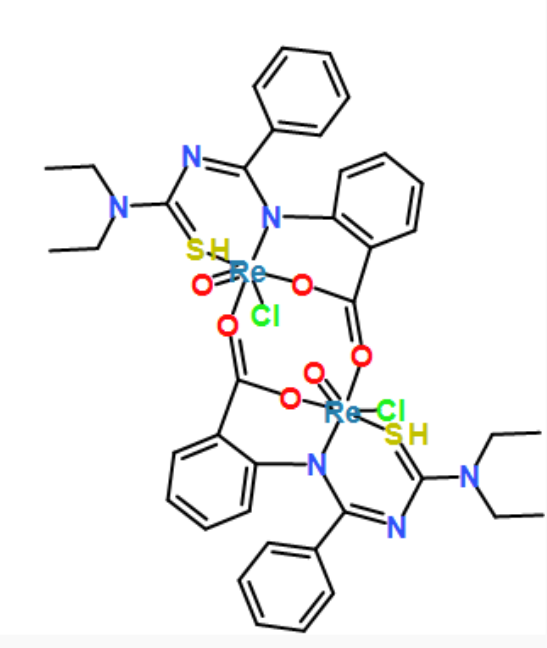
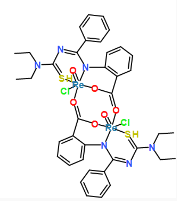
Kamada-Kawai and Stress Majorization are based energy function minimisation model. The energy function minimisation model uses the spring system to minimise the difference between the visual distance and theoretical graphed distance, and this is accomplished by solving (minimising) an energy function. In the optimization, if the visual distance between a pair of nodes is closer than their corresponding theoretical graphed distance, they repel each other; otherwise, they attract each other. For most molecules, both algorithms do a good job. But for large graphs, Stress Majorization is usually faster and better than KK algorithm.
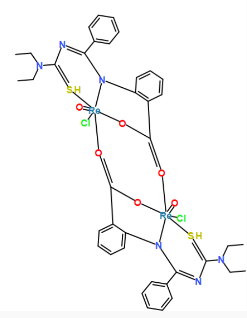
While FR algorithm doesn't use theoretical graphed distance for optimization, it uses two forces, with the attractive force (fa) and repulsive force (fr). Attractive forces occur between adjacent vertices only, whereas repulsive forces occur between every pair of vertices. Each iteration computes the sum of the forces on each vertex, then moves the vertices to their new positions. Because FR algorithm doesn't use theoretical graphed distance to constrain the edge length, so the molecule looks very strange.
[Re]123(=O)([O]=C4c5c(cccc5)N5[Re](=O)(S=C(N=C5c5ccccc5)N(CC)CC)(Cl)(O4)[O]=C(c4c(cccc4)N2C(=NC(=S3)N(CC)CC)c2ccccc2)O1)Cl
coordinates generated by force-directed layout algorithms. fr, kk and stress, respectively
Shortly, The algorithms with theoretical graphed distance constraint are better for molecule 2D coordinates generation, for example KK layout and Stress Majorization.
Position initialization
The initial positions of nodes affect the performance of force-directed layout. A good initialization will make forced-directed layout generate better coordinates and speed it up. To improve the performance of force-directed layout and compare the effects of initial layout, three different position initialization algorithms were developed. As listed in below table. Circular initialization is easy to implement, but sometimes it cause edge crossing . Generally, planar initialization is better circular initialization, can avoid many edge crossing that happened in circular initialization and it is also easy to implement. Hybrid initialization is the best of three and make the graph looks better for chemists, but it is hard to detect the graph structure and initialize the nodes.
COC(=O)[C@@]12N=C(C(=O)O1)/C(c1ccccc1)=C1/C=CC(=N1)C(c1ccccc1)=c1cc/c([nH]1)=C(\c1ccccc1)c1ccc([nH]1)[C@H]2c1ccccc1
| Initialization | Picture | Description |
|---|---|---|
| Circular | 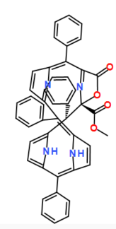 |
initialize all nodes as a circle |
| Planar | 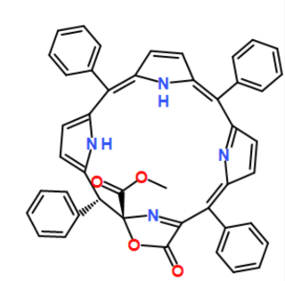 |
initialize every internal MCB as a planar circle |
| Hybrid | 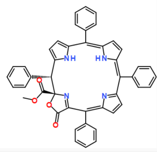 |
rapidly detect the structure of graph, initialize the graph according to the graph structure and chemical graph representation |
